Windows Vista OEM activation crack method requires a SLP 2.0 (System Locked Preinstallation 2.0) compliant BIOS motherboard. New branded OEM computer comes with one, or offers not-so-old motherboard a BIOS free upgrade to the one that supports SLP 2.0 with SLIC table and signed Windows Market (OEM ID and Table ID). If you are using older computer or DIY motherboard, you’re not out of luck though. Chinese hackers have managed to mod the BIOS to replace or add in the SLIC (Software Licensing Internal Code) table into the ACPI table. However, the replacement of existing ACPI table may cause loss of certain features, while addition of SLIC table may incompatible on computer with different size of memory, as BIOS is hard patched with the SLIC’s table physical memory address which restrict the mod BIOS to the machine it’s been modified only.
So, the method to mod BIOS for Windows Vista OEM support with previously used static SLIC memory address is problematic as the memory address will be changed when the memory size changed, and users need to modify the SLIC address in ACPITBL.BIN or else they won’t be able to boot into the system, disallowing mass circulation of the mod OEM BIOS. Thus the Chinese hackers refine the technique to allows dynamic physical memory address allocation of SLIC table is been used. With dynamic memory allocation, physical memory size can be changed without any consent of BIOS non-compliant. Beside, previous method of adding SLIC table may require users to flash BIOS into ROM 2 times, first with the mod BIOS and later with the original BIOS, while the BIOS with this refined method with dynamic memory address register requires only one flash at most.
Tools and utilities required:
- MODBIN6
- CBROM219
- WinHEX
- Hiew 7.4 (Hiew32) (only for Award BIOS, if you have Hiew32 you no longer require IDA 5.0)
- IDA 5.0
- UltraEdit
The instruction to create a mod Vista OEM BIOS with dynamic memory address allocation capability is complicated, and recommended for expert only. Beside, this article is translated from documents in Chinese, so the accuracy of the translation is not guaranteed. If you really want to make your BIOS to be able to activate OEM version of Windows Vista, try the ready-mod BIOS (with static address), software based Vista Loader OEM BIOS emulator, or software based OEM BIOS Emulation Toolkit. Other popular Vista crack include TimerLock which automatically apply TimerStop driver. This tutorial is proof of concept only, as each BIOS is different, and hence the values or steps or things modified may be different.
Warning: Alteration to BIOS may invalidate warranty, cause computer to unable to boot up or other irrecoverable effect. Do it at your own risk.
If you need help on mod BIOS for Vista activation, check out this thread.
- Create a temporary folder (Vista or BIOS is you like) at root directory (C:\).
- Download CBROM 2.19 (depending on where you download, it may need to rename the executable to cbrom.exe as illustrated in this article), MODBIN6 2.01.01, SLIC.BIN (named acpislic.bin which can be varied, which is the SLIC table portion of BIOS) from download links above, and place them in the temporary folder.
- Extract, export or save the XXXXXXXX.BIN (name can be changed, which is the motherboard BIOS that you want to hack for Windows Vista OEM activation). Easier way is to simply download the BIOS firmware from the computer or motherboard’s manufacturers such as ASUS, Gigabyte, MSI, Acer, HP, Dell, Lenovo and etc.
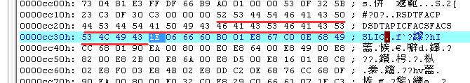
- Determine which BIOS portion of file is the field of RSDT…FACS located:
- In elevated command prompt (or disable UAC), type the following command:
CBROM.EXE XXXXXX.BIN /d
You will see something like below screencap:
CBROM V2.19 (C)Award Software 2001 All Rights Reserved.
******** XXXXXXXX.BIN BIOS component ********
No. Item-Name Original-Size Compressed-Size Original-File-Name
=====================================================
0. System BIOS 20000h(128.00K) 13B3Eh(78.81K) 83IID318.BIN
1. XGROUP CODE 0DFF0h(55.98K) 0993Ch(38.31K) awardext.rom
2. ACPI table 043E5h(16.97K) 01A46h(6.57K) ACPITBL.BIN
3. EPA LOGO 0168Ch(5.64K) 002AAh(0.67K) AwardBmp.bmp
4. YGROUP ROM 0F570h(61.36K) 0482Dh(18.04K) awardeyt.rom
5. GROUP ROM[ 0] 04CD0h(19.20K) 02261h(8.59K) _EN_CODE.BIN
6. Other(404E:0000) 03476h(13.12K) 00EB4h(3.68K) 64N8IIP.BMP
7. Other(404F:0000) 0345Dh(13.09K) 008B9h(2.18K) 64N8P4P.BMP
8. Other(4050:0000) 0345Dh(13.09K) 008CCh(2.20K) 64N8P4HT.BMP
9. Other(4051:0000) 04286h(16.63K) 00A7Eh(2.62K) 64N8P4E.BMP
10. Other(4052:0000) 04286h(16.63K) 00B58h(2.84K) 64N8P4HE.BMP
11. Other(4053:0000) 0345Dh(13.09K)007D9h(1.96K) 64N8ICPD.BMP
12. PCI ROM[A] 0D000h(52.00K)07DA8h(31.41K) RTM8100.LOMTotal compress code space = 4B000h(300.00K)
Total compressed code size = 31788h(197.88K)
Remain compress code space = 19878h(102.12K)** Micro Code Information **
Update ID CPUID | Update ID CPUID | Update ID CPUID | Update ID CPUID
——————+——————–+——————–+——————
PGA478 2E 0F29| - In above case, inside XXXXXXX.BIN, there is no ggroup.bin (where “RSDTFACPDSDTAPICHPETMCFGFACS” or similar ACPI tables index field is located), so RSDT…FACS field is located inside the system BIOS byte code中, and to modify this need to use MODBIN6. If your BIOS contains ggroup.bin, you can use CBROM to extract and seperate ggroup.bin BIOS part as file.
Below is the sample CBROM output of “CBROM.EXE XXXXXX.BIN /d” command for BIOS with ggruoup.bin (Gigabyte GA-G1975X BIOS as example):
No. Item-Name Original-Size Compressed-Size Original-Fi
================================================
0. System BIOS 20000h(128.00K)1492Ah(82.29K)G1975X.BIN
1. XGROUP CODE 0F7B0h(61.92K)0A8E6h(42.22K)awardext.rom
2. EPA LOGO 0168Ch(5.64K)0030Dh(0.76K)AwardBmp.bmp
3. GROUP ROM[18] 00EF0h(3.73K)00B77h(2.87K)ggroup.bin
4. YGROUP ROM 07140h(28.31K)04D7Ch(19.37K)awardeyt.rom
5. FNT1 ROM 02D28h(11.29K)02038h(8.05K)font1.awd
6. FNT2 ROM 03278h(12.62K)01F18h(7.77K)font2.awd
7. FNT3 ROM 025FCh(9.50K)017FBh(6.00K)font3.awd
8. GROUP ROM[ 0] 06010h(24.02K)02787h(9.88K)_EN_CODE.BIN
9. GROUP ROM[ 1] 06510h(25.27K)02A1Fh(10.53K)_FR_CODE.BIN
10. GROUP ROM[ 3] 06420h(25.03K)02A75h(10.61K)_GR_CODE.BIN
11. GROUP ROM[ 4] 068D0h(26.20K)02A74h(10.61K)_SP_CODE.BIN
12. GROUP ROM[ 8] 04EF0h(19.73K)02575h(9.36K)_B5_CODE.BIN
13. GROUP ROM[10] 04F60h(19.84K)025E9h(9.48K)_GB_CODE.BIN
14. GROUP ROM[11] 05E50h(23.58K)02A85h(10.63K)_JP_CODE.BIN
15. PCI ROM[A] 0F200h(60.50K)09594h(37.39K)ICH7RAID.BIN
16. PCI ROM[B] 10000h(64.00K)09A15h(38.52K)b169d.pxe
17. LOGO1 ROM 00B64h(2.85K)00520h(1.28K)dbios.bmp
18. PCI ROM[C] 04000h(16.00K)02287h(8.63K)ITE8212.ROM
19. Other(4067:0000) 01AADh(6.67K)00B75h(2.86K)PPMINIT.ROM
20. OEM0 CODE 025B3h(9.42K)01B37h(6.80K)dbf.bin
21. GROUP ROM[24] 00132h(0.30K)0011Eh(0.28K)SPECIAL.FNT
22. ACPI table 09640h(37.56K)0352Ch(13.29K)ASUSACPI.BINTotal compress code space = 67000h(412.00K)
Total compressed code size = 57613h(349.52K)
Remain compress code space = 0F9EDh(62.48K)** Micro Code Information **
Update ID CPUID | Update ID CPUID | Update ID CPUID | Upd
——————+——————–+——————–+—–
SLOT1 0A 0F32| PGA423 2C 0F25| 00000000 00000000 0000
00000000 00000000 0000 0000| 00000000 00000000 0000
00000000 00000000 0000 0000| 00000000 00000000 0000
00000000 00000000 0000 0000| 00000000 00000000 0000
00000000 00000000 0000 0000| 00000000 00000000 0000
00000000 00000000 0000 0000| - For BIOS with ggroup.bin, extract the ggroup.bin with the following command:
CBROM.EXE G1975X.bin /group18 extract
You should see the following output as below screenshot:
CBROM V2.19 (C)Award Software 2001 All Rights Reserved.
Enter an extract file Name :(ggroup.bin)
[GROUP] ROM is extracted to ggroup.bin - Separate, save and extract the ACPITBL.BIN by using the following command:
CBROM.EXE 050318.BIN /acpi extract
You should see the following output from CBROM:
CBROM V2.19 (C)Award Software 2001 All Rights Reserved.
Enter an extract file Name :(ACPITBL.BIN)
[ACPI] ROM is extracted to ACPITBL.BIN - For BIOS without ggroup.bin (those with ggroup.bin can skip this step), launch MODBIN6, select XXXXXXXX.BIN (Must be named in .BIN extension, if not rename it. It’s the BIOS to modify to add in the SLIC table so that it’s SLP 2.0 compliant.). Do not close the window of MODBIN6, and wait for the ORIGINAL.BIN to be extracted and created in the temporary folder.
- In elevated command prompt (or disable UAC), type the following command:
- Follow the below instructions to modify ACPITBL.BIN:
- Run UltraEdit and open ACPITBL.BIN BIOS image file.
- Search text for RSDT.
- Behind RSDT is the byte that indicates the length of RSDT table. Add 4 to this number in HEX format. For example, if the value indicated is 002C, modify and edit the value to become 0030. Note that the reverse sequence of pairs when keying in UltraEdit Hex editor (i.e. enter as 30 00 instead of 00 30).
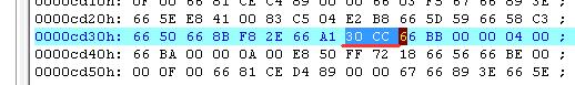
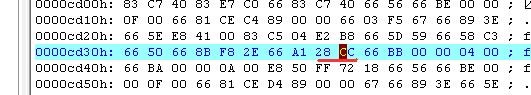
- Insert (not replace) additional 4 bytes of 00 value after the original length (002C) of RSDT table (normally in front of FACPt, or FXCPt for certain Gigabytes mobo). You can copy and paste the 4 bytes of 00 from other location to this location. This modification and alteration is to provide space to store the SLIC table in future steps, so remember this address (for this guide, assume this location is SLICaddress). In this example, SLICaddress value is 002C.
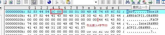
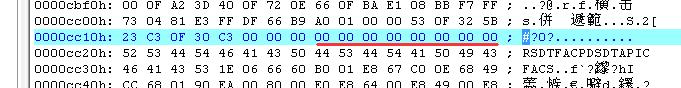
Before modification of ACPITBL.BIN in UltraEdit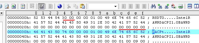
After modification of ACPITBL.BIN in UltraEdit to allocate space for SLIC table. - Check the total length of ACPITBL.BIN if the length can be divided in full by 4. If not, add 1 to 3 bytes of 00 at the end of the BIOS image file so that the length can be divided by 4 without any remainder. This is to ensure that after merging with SLIC.BIN image file, the header address of SLIC table can be divided by 4 without remainder too.
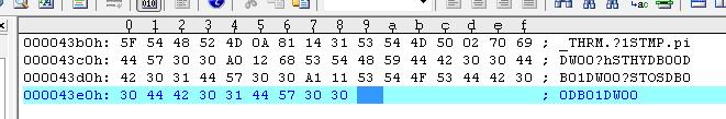
Check if the length of ACPITBL.BIN (the last address of the file + 1) can be divided by 4 without remainder. In this example, before this step modification, the last byte has HEX address of 43E8, so the length of the file is 43E9, cannot be divided by 4 in full without remainder.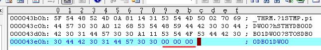
After 4 division check modification, added 3 00 value bytes. - Modify OEM_ID and OEM_Table_ID according to your requirements (normally _ASUS_ and Notebook). Refer to improved add SLIC table instruction at step 8 of part 2 for more information.
- Save the file.
- Execute the following command to merge and patch the SLIC table content with the modified ACPITBL.BIN to get the final working copy of ACPITBL.BIN:
COPY ACPITBL.BIN /B + SLIC.BIN /B ACPI.BIN /B
Note: According to your requirement, use the correct ACPI.BIN, i.e. ASUS for ASUS OEM ID, Lenovo for Lenovo OEM ID and etc.
- Follow the below steps to find the position of the space that temporarily store the value of the address of headers of every tables in the code of ORIGINAL.BIN or ggroup.bin. This address will be assumed as TempBuffer_Address:
- Run Ultract to open ORIGINAL.BIN or ggroup.bin.
- Execute IDA.
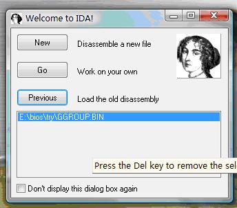
- Click on Go to enter IDA. Then select and open ORIGINAL.BIN file.
- In the “Load a new file” dialog box, under the section of “Processor type”, pull down the menu and select “Intel 80×86 processors:80686p”.
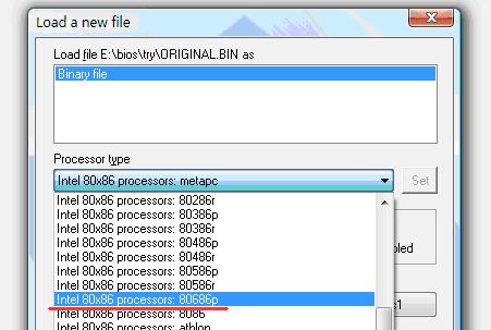
- After selected, hit the “Set” button to the right.
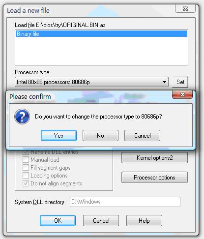
- Click on “OK” button, and then hit on “Yes” button when asked to confirm “Do you want to change the processor type to 80686p?”
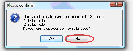
- In dialog box asked to confirm “Do you want to disassemble it as a 32-bit code?”, press on “No” button as manipulation will be done in 16-bit mode.
- In the Strings Window to the right, find and locate the RSDT…FACS character string sequence, and double click on it.
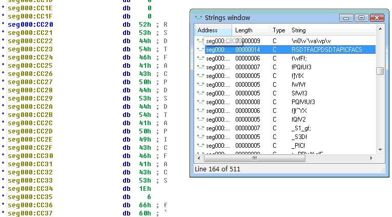
- Position the cursor at the location of the R character. Then press “A” key, and then RSDT…FACS character string will be displayed. This text sequence of RSDT…FACS will be called ACPItables.
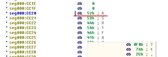
Positioning cursor at the line of R.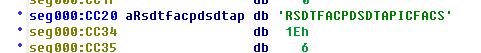
After pressing A key. - Position the cursor after the RSDT…FACS string ACPItables (db 1EH).
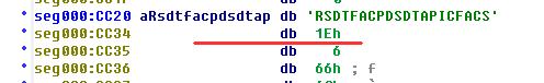
Press the “C” key. A block of Assembly code will be displayed.
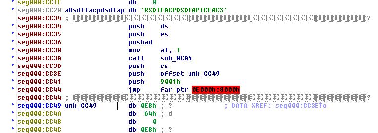
- But there is remaining code that hasn’t been disassembled into Assembly code. So position the cursor at the first remained assembled code. In this case, it’s line of unk_CC49 after the RSDT…FACS string ACPItables provided by db 1Eh. Then press the “C” key to convert and disassemble the remaining BIOS byte code.
- Move the cursor across the lines of the following “CALL” block.
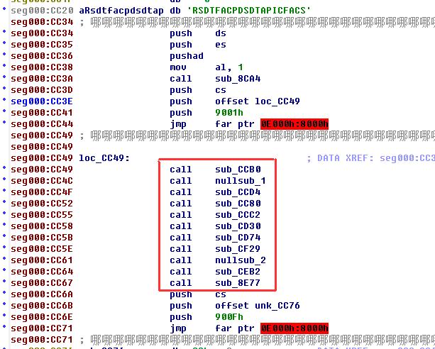
- Watch out for the “CALL” line that can pop up code like below:
push eax
push cx
push ebp
xor ebp, ebp
mov cx, TABLE_Numbers (temporarily use TABLE _Numbers to represent a value)
mov edi, eaxIn this example, it’s the line of “call sub_CCD4”.
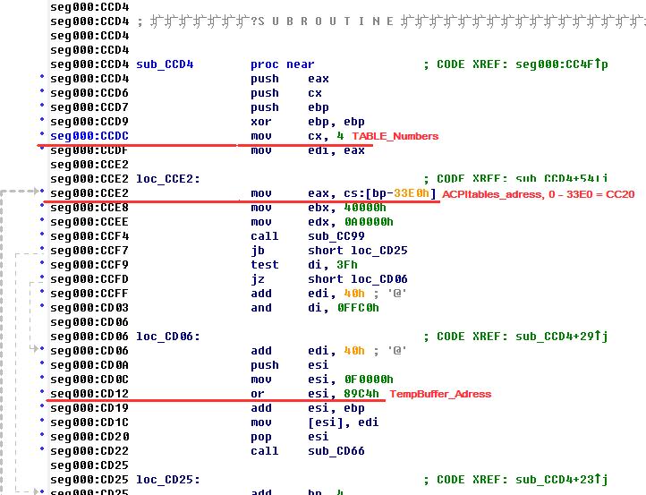
- Double click on sub_CCD4 to go to the code section of sub_CCD4. If the current display mode is in graphic, right click and select “TEXT View” on the context menu to switch to text mode.
- Inside this block of code, retrieve the 3 important variables – TABLE_Numbers,ACPItables_adress,TempBuffer_Adress,and record their value. In this example, the value of the variables are 4, CC20, 89C4 respectively, where addresses are approximately located at CCDC,CCE2, CD12 respectively.
- Use the value of TempBuffer_Adress (89C4 from step above) to match with each table in RSDT…FACS text string, with increment of 4 after each table (matching table). For example:
89C4 RSDT
89C8 FACP
89CC DSDT
89D0 APIC
89D4 FACS
89D8
89DCThe previous block of code duplicates the required tables in ACPITBL BIOS image according to RSDT…FACS string into a free memory address, and store these value of addresses in space specified by TempBuffer_Address, and then eventually fill these addresses into some specific tables. So during this process, the storing address value of TempBuffer_Address has to be ensure that cannot and is not changing, or else mod BIOS will fail.
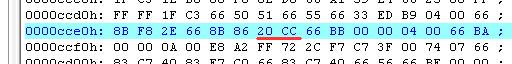
- Switch to UltraEdit, and press Ctrl-F keyboard shortcut to search for D889 (i.e 89D8 value, the value of the memory space location after FACS, where it’s a reverse with low byte in front and high byte behind). Pay attention to a few location (82D4, CC91) that lower than FFFF. Most likely you will find it at a few location. If you cannot find any D889 (stored value of 89D8), then you can use directly the address (89D8) located behind the address used to store FACS (89D4). Which mean SLIC table will be appended immediately behind FACS, with string become something like RSDT…FACSSLIC, and can do so by find a location to put this string (move forward 4 bytes or use new location).
- However, if you located code like the following near the location of CC91 in IDA, which mean the section of code is used right after “call sub_CCD4”, and use up the memory address of 89D8.
seg000:CC80 sub_CC80 proc near ; CODE XREF: seg000:CC52p
seg000:CC80 push ds
seg000:CC81 mov ax, 0F000h
seg000:CC84 mov ds, ax
seg000:CC86 assume ds:nothing
seg000:CC86 add edi, 10h
seg000:CC8A and di, 0FFF0h
seg000:CC8D mov large ds:89D8h, edi
seg000:CC95 pop ds
seg000:CC96 assume ds:nothing
seg000:CC96 retn
seg000:CC96 sub_CC80 endpIn this case, use UltraEdit to search for next available address from step above (DC89 for 89DC). If nothing is found, this memory address location can be used to put SLIC table. The problem with this memory address allocation is that there is a skip address or space (89D8) between FACS and SLIC tables. To fix this issue, add the text string of FACSSLIC instead of just SLIC, as FACS table is small and won’t use too much memory.
- After modification, you will have the ACPI table index string as either RSDT…FACSSLIC or RSDT…FACSFACSSLIC. To accomodate the first instance of string, the whole string can be move forward (to the front) by 4 bytes as mentioned above. Otherwise, a new location has to be identified to store the new text string. But in the later case where 8 bytes have been added, so we need to find a new location for this longer string. In this example BIOS, there is 11 empty bytes (00) in front of the ACPItables_address (located at CC20). This empty bytes should be unused, beside, in UltraEdit, there is no code that uses the CC18 or CC1C two address locations. So, the new string can be put forward to location with starting address as CC18.
Moving RSDT string forward 8 bytes to accommodate new 8 bytes SLIC table. - Now the anchor address of the RSDT…SLIC string has been moved, and the initial bit address of the string has to be made known to the system. Search in UltraEdit for “20CC” (the original address), you will find it at CCE2 address as found out from step above. Change the 20 to 18 to make it “18CC” (address always reverse when indicate) to indicate the new starting address.
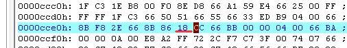
After changing 20 to 18 to indicate new location address. - Since the RSDT string has been moved, the location of FACS table has also moved too (refer to figures above). The original address of FACS table is CC30 while new address is CC28 or CC2C. And, in the rest of the code, the address is been used. So the address of FACS has to be modified too.
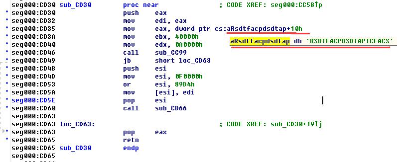
The value for the original address is address of ACPItables_address (CC20) + 10 which equals to CC30. In UltraEdit, search for 30CC, which should be found at around reference location of CD35. Change the 30CC to 28CC (for CC28) or 2CCC (for CC2C).
- Next, SLIC table has to be added to the address that is been reserved for it in RSDT tables string in ACPI.BIN.
seg000:CD74
seg000:CD74 sub_CD74 proc near ; CODE XREF: seg000:CC5Bp
seg000:CD74 push edi
seg000:CD76 push esi
seg000:CD78 mov esi, 0F0000h
seg000:CD7E mov eax, [esi+89C4h]; Fill RSDT address to RSDT Ptr
seg000:CD86 or eax, eax
seg000:CD89 jz loc_CE32
seg000:CD8D mov [esi+89C0h], eax ; RSDT Ptr
seg000:CD95 mov eax, [esi+89CCh]; Fill DSDT address to FACP
seg000:CD9D or eax, eax
seg000:CDA0 jz loc_CE32
seg000:CDA4 mov edi, [esi+89C8h]; FACP
seg000:CDAC mov es:[edi+28h], eax
seg000:CDB2 mov eax, [esi+89D4h]; Fill FACS address to FACP
seg000:CDBA or eax, eax
seg000:CDBD jz loc_CE32
seg000:CDC1 mov edi, [esi+89C8h] ; FACP
seg000:CDC9 mov es:[edi+24h], eax
seg000:CDCF mov eax, [esi+89C8h]; Fill FACP address to RSDT+24
seg000:CDD7 or eax, eax
seg000:CDDA jz loc_CE32
seg000:CDDE mov edi, [esi+89C4h] ; RSDT
seg000:CDE6 mov es:[edi+24h], eax
seg000:CDEC cmp byte ptr [bp+1BFh], 7
seg000:CDF1 jnz short loc_CDFE
seg000:CDF3 test dword ptr [bp+1C6h], 200h
seg000:CDFC jz short loc_CE2F
seg000:CDFE
seg000:CDFE loc_CDFE: ; CODE XREF: sub_CD74+7Dj
seg000:CDFE test byte ptr [bp+2EBh], 4
seg000:CE03 jz loc_CE2F
seg000:CE07 mov eax, [esi+89D0h] ; Fill ACPI address to RSDT+28
seg000:CE0F or eax, eax
seg000:CE12 jz short loc_CE2F
seg000:CE14 mov edi, [esi+89C4h] seg000:CE1C mov es:[edi+28h], eax
seg000:CE22 mov edi, eax
seg000:CE25 push es
seg000:CE26 call sub_B4BB
seg000:CE29 pop es
seg000:CE2A jb short loc_CE2F
seg000:CE2C call sub_5077From the matching table that matches the ACPI tables to respective memory address made in step above, use it to match against the code above. Here, none of the code representing process to fill the data value of 89DC address to RSDT table, so the following code needs to be added:
mov eax, [esi+89DCh] ; 8 bytes
mov edi, [esi+89C4h] ;8 bytes
mov es:[edi+2Ch], eax; 6 bytes, the value of the length of the ACPI tables (SLICaddress which is 2C).Addition of these code cannot affect the the rest of the functions’ address, so a few not critical code has to be deleted to free up some space.
In the above code, after every mov eax, [esi+????h], it’s followed by the block of code as below:
or eax, eax ; 3 bytes
jz short loc_CE2F ;2 bytesThese are verification bits which is precaution method to prevent collapse or fault of system. However, after analysis, there is pair of verification bits that can be removed after reorganization of RSDT table. Thus, remove the data verification parts of RSDT table which is located as below:
seg000:CDD7 or eax, eax ; 3 bytes
seg000:CDDA jz loc_CE32 ;2 bytesand
seg000:CE0F or eax, eax ; 3 bytes
seg000:CE12 jz short loc_CE2F ;2 bytesAfter doing this, only 10 bytes of space is freed up, but the mod requires 22 bytes. In the code above, whenever it fills up the code for RSDT table, it will execute this command:
mov edi, [esi+89C4h] ; 8 bytes
But, it does not alter the value of the register or variable when twice it executes the process to fill in the RSDT table. So this command can be executed only once. In fact, if the new code is placed here, this command for the new code can be skipped too. With this adjustment, there will be enough blank space been emptied. Extra space can then be filled up with blank command (90 and nop). The final code will look like this:
seg000:CDCF
mov eax, [esi+89C8h]; fill up FACP address to RSDT+24
mov edi, [esi+89C4h] ; RSDT
mov es:[edi+24h], eax
mov eax, [esi+89DCh] mov es:[edi+2Ch], eax
nop
nop
nop
nop
cmp byte ptr [bp+1BFh], 7
jnz short loc_CDFE
test dword ptr [bp+1C6h], 200h
jz short loc_CE2F
test byte ptr [bp+2EBh], 4
jz loc_CE2F
mov eax, [esi+89D0h] ; fill up ACPI address to RSDT+28
seg000:CE22 mov es:[edi+28h], eax the address for this command cannot be changed.The address location of the code that will be deleted and inserted has to be remembered:
seg000:CDD7 or eax, eax ; 3 bytes
seg000:CDDA jz loc_CE32 ;2 bytes
5 bytes starting from CDD7seg000:CE0F or eax, eax ; 3 bytes
seg000:CE12 jz short loc_CE2F ;2 bytes
seg000:CE14 mov edi, [esi+89C4h] 5+8 bytes staring from CE0Fseg000:CDEC cmp byte ptr [bp+1BFh], 7
Original location of CDEC to insert all needed code here - The mod process is done, now go back to UltraEdit for last step address modification. This step is best done from bottom up to prevent the code below been jumbled when replacing the front part.

Firstly, remove 13 bytes starting from CE0F.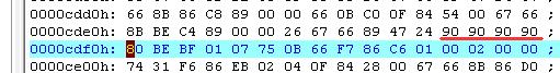
Then insert any 4 bytes of random data at the CDEC, then change the value to 4 90 (90h=nop).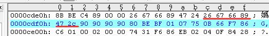
Copy the code at CDE6 to CDEB, and paste it to address starting from CDEC to reflect the command used: mov es:[edi+2Ch], eax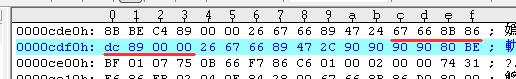
Copy the code at CDCF to CDD6, and paste it to address starting from CDEC to reflect the command used: mov eax, [esi+89DCh]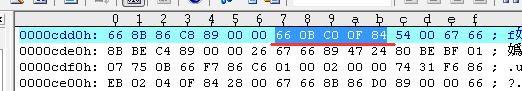
Lastly, remove 5 bytes starting from CDD7. - Save the code.
- Verify that the modification of code is correct by using IDA to check if the modified code is correct. If yes, repack the code into the BIOS file.
Disclaimer: This article is for informational and educational purpose only.
 Tip and Trick
- How To Download HBO Shows On iPhone, iPad Through Apple TV App
- Windows 10 Insider Preview Build 19025 (20H1) for PC Official Available for Insiders in Fast Ring – Here’s What’s News, Fixes, and Enhancement Changelog
- Kaspersky Total Security 2020 Free Download With License Serial Key
- Steganos Privacy Suite 19 Free Download With Genuine License Key
- Zemana AntiMalware Premium Free Download For Limited Time